I2C and the Raspberry Pi

Well I2C was the obvious next candidate for a driver. Another active Raspberry Pi coder, Frank Buss, wrote some nice driver code but sadly didn’t integrate it with Linux’s own i2c driver framework. It worked, though not as I wanted it. He did the hard work. I then took his code (with his permission of course) and wrote a Linux i2c driver for it today. It works! You can grab it at:

https://github.com/bootc/linux/tree/rpi-i2cspi

This tree contains the latest SPI and I2C code. Here’s how to use it:

Continue reading

SPI on the Raspberry Pi (again)

I’ve kept working on my Raspberry Pi SPI driver and the last few updates should be quite interesting to people following this. Aside from fixing a silly bug a few days ago (I was releasing the chipselect lines when I shouldn’t have been), I’ve done some work to no longer require the switchPinCtrl tool and to implement IRQ mode.

IRQ mode means that the driver no longer uses 100% of the CPU when doing transfers, running a busy loop checking the flags to read/write the FIFO. Instead, it waits until the SPI hardware tells it that it needs to do something, and means other software can get on and do things at the same time. In testing SPI transfers to/from some AT45DB161D flash memory chips, I’m using less than 5% of the Raspberry Pi’s CPU including the top process.

I’m testing the SPI with those chips at 7.8 MHz (250 MHz ÷ 32) and it is working very reliably indeed, with no data errors reading and writing random data. At 15.6 MHz the process was quite unreliable, but I think that’s more to do with my jumble of jumper wires just not managing those sorts of speeds which is rather predictable. I have also tested with a DS3234 RTC chip which works very well.

I’ve also incorporated a small snippet of code to put the SPI pins in the correct ALT mode (ALT 0) so that the SPI hardware can drive them, instead of them being set up as GPIO pins. Previously I asked that folks run a command-line tool to do this but this was leading to a great deal of confusion (especially on my part!) so I put the code into my driver. This is not where the code belongs, really this should be in a pinmux/pinctrl driver, but it’ll do for now.

Update: Updated the link to the git branch, now points at the branch with both the I2C and SPI drivers in.

SPI on the Raspberry Pi

Over the last few days I have been writing a driver for the Raspberry Pi’s SPI peripheral. This driver will let you use the SPI pins on the GPIO header properly rather than relying on bit-banging. Someone already wrote a driver but it was incomplete and I didn’t much care for the code, so I decided to roll my own.

One of the primary advantages of my code at the moment is that the clock speed on the SPI port can be set properly, rather than being hard-coded to an invalid value. The SPI clock speed is determined by dividing the SPI peripherals reference clock (250 MHz) by a power-of-2 divider between 2 and 65536. This gives you a number of speeds from 3.8 KHz to (theoretically) 125 MHz. Given a clock rate in Hz, my driver will pick the fastest speed possible less than or equal to the given speed, so if you request 500 KHz, you get 488 KHz instead (250 MHz ÷ 512).

You can find all the necessary patches in the rpi-spi branch on my GitHub.

Please note: If you want to use this code you’ll need to download switchPinCtrl from the person who wrote the other SPI driver to put the SPI pins into the right mode. If you don’t do this, the pins will remain set up as GPIOs and you will not get anything from the SPI driver on those pins. This will be fixed when I get round to writing a pin control driver so that this can be managed from within the kernel. This is on the TODO list.

Also on the TODO list for this driver is interrupt-driven mode which should greatly reduce the CPU load.

Raspberry Pi Serial Console

Raspberry Pi Serial Console

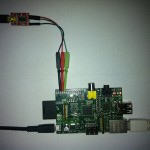
I’ve had a few questions about how I wired up my serial console on my Pi, so here’s a quick post about it.

The best place to start is the page on elinux.org that details the pins on the GPIO header (RPi low-level peripherals). You’ll notice you need pins 8 and 10 for the Pi’s TX and RX pins, you’ll also need a ground point which you can find on pin 6. You can then hook those straight into a 3.3V USB to serial converter’s GND, RX and TX pins and get a console running. Note that you need to connect the TX pins to the RX pins or you won’t be getting any output. Do not use a 5V cable. Do not connect the power pin on the FTDI adapter to any of the Pi’s power pins either.

Continue reading

Updated Raspberry Pi Wheezy Image

I’ve updated my Raspberry Pi Minimal Wheezy image to fix the problem with udev and network interfaces:

wheezy-mini-2012-05-11.img.gz (113MB)

The root password is unchanged from last time: raspberrypi

Change Log

  • Removed my Raspberry Pi’s eth0 from /etc/udev/rules.d/70-persistent-net.rules

Please note: If you used my 2012-05-08 image and have fixed the rules file there is no need to upgrade.

Continue reading

Raspberry Pi

I was lucky enough to finally receive my Raspberry Pi last Friday. I ordered it from Farnell as early as I possibly could, and my order was dated 08:34:24 29/02/2012. Of course I’ve been playing with it since, and have mostly been working on the kernel – getting things cleaned up a bit and upgraded a bit. So the first thing to announce is I’ve got a little stash of Raspberry Pi-related stuff available for people to try.

Linux 3.2.16 kernel

The main improvement is that you can boot the compressed kernel and that early printk works. Using either of these caused the RPi to hang at boot due to the early console code being badly broken, but my changes (available on GitHub) initialise the serial port (115200 Kbps 8n1) if you boot the compressed image and give you serial output as soon as possible. This is very useful for debugging the kernel.

I’ve also rebased the 3.1.9-based official tree against 3.2.16 to bring it more into line with what Debian Wheezy expects at the moment. Simon has his own tree where we’re working on 3.3 and more recent kernels, ideally aiming for mainline inclusion at some point in the future. This is a big job though.

So without further ado, grab yourself the pre-built 3.2.16 kernel and install it like this (as root):

  1. dpkg -i linux-image-3.2.16-rpi1+_1_armel.deb
  2. Backup your /boot/kernel.img.
  3. cat first32k.bin /boot/vmlinuz-3.2.16-rpi1+ > /boot/kernel.img
  4. Reboot

Please let me know if you have any issues with this kernel (that you don’t also have with the stock kernel)!

Minimal Debian Wheezy disk image

In my travels with the Raspberry Pi I found that the official Debian image wasn’t to my liking. Not only does it have lots of unnecessary (for me) software installed, but certain configuration files are badly mangled (such as /etc/passwd and family). The image is also based on Squeeze, though I admit it’s easy enough to dist-upgrade to Wheezy. Regardless, I decided to start from scratch using debootstrap (and working around some interesting issues) I built a minimal Debian Wheezy image.

This has the bare minimum changes from a plain debootstrapped system to get a working Raspberry Pi. It runs DHCP on eth0 at boot and runs ntpd, but does not have openssh-server installed. It starts consoles on both the serial port (115200 8n1) and the HDMI display. The time zone is set to UTC. The kernel, of course, is my 3.2.16 kernel from above.

Update 2012-05-11: I have updated my image to fix the udev problem mentioned below. Please see my latest post about it.

Download wheezy-mini-2012-05-08.img.gz (113M). The root password is raspberrypi.

Please note: There is one known issue with the above image which means that your eth0 will be renamed to eth1 and networking will not be brought up automatically. This is easy to fix: just edit /etc/udev/rules.d/70-persistent-net.rules and remove the two sets of rules with their comments at the end of the file, then reboot. I have created an updated image that fixes this problem.

World IPv6 Day

Today is World IPv6 Day. The idea is that lots of companies will be enabling IPv6 on their web sites and other public services to make sure that everything works OK. IPv6 is a new Internet Protocol, to replace the now-obsolete IPv4, because we’ve nearly run out of addresses the protocol can use.

My home network has been fully IPv6 enabled since we moved to Devon all of 5 years ago (through my fantastic ISP, Andrews & Arnolds). I’ve been happily browsing away on the small number of web sites that offer IPv6 outside of World IPv6 Day. My day-to-day Googling and YouTubing have all been IPv6 for a long time now. Today sees us use Facebook over IPv6 and a bunch of other sites, but without looking it up I don’t even know which – you can’t tell the difference.

But one thing that isn’t IPv6 enabled yet, to my great chagrin, is my server. This web site and all the others I run, my email, my customers’ virtual machines… None of that is on IPv6, because the ISP my server is colocated with cannot get its act together. I have emailed RapidSwitch (IWNL) on multiple occasions asking when IPv6 will be available and they just keep burying their head in the sand. Apparently I’m one of only a small handful of customers who have asked for this, so there’s no ‘business’ reason to implement it. Well when it finally hits them in the face they won’t be ready for it and it’ll be a scramble. Great joy.

Update: I should add that I have a Linode virtual machine on a server somewhere in New Jersey, which is my “disaster recovery” machine in case anything should happen to the main server. That one is fully IPv6 enabled, so secondary DNS and my backup MX are reachable over IPv6. At least someone can do it right!

I guess I wait for and put up with the mad dash when it needs to be done, or find an alternative place to host my server and deal with all that fallout.

Happy IPv6 day!

PolyController Update

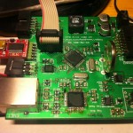
PolyController Main Board

PolyController Main Board

I haven’t posted about this for a while, but the project is definitely progressing. The hardware is complete—PCBs have been manufactured, I’ve soldered them up, and they have been fitted into enclosures. The firmware is also progressing well, though much slower than I had hoped due to being quite busy at the moment! The PCBs have had quite a few minor changes since I last posted pictures, especially on the main controller PCB. Some of the connectors were relocated and quite a few mistakes were fixed before production. Even so, as with almost any first revision PCB, there have been a few mistakes…

The Mistakes!

The first mistake is on the 32.768KHz clock line from the RTC to the AVR microcontroller. The clock output is open drain on the RTC, so this requires a pullup resistor to get a meaningful signal. The AVR I/O port has an internal pullup that can be enabled if required so I thought I could use that, but it turns out that doesn’t work if you use the port as a clock input rather than a general purpose I/O. This is easily fixed with greenwire and a 1K resistor.

Continue reading

Hacking the Emprex NSD-100

Emprex NSD-100 P2P Download Device

I recently got an Emprex NSD-100 from eBuyer, as they were dirt cheap. The purpose of this device is to sit on your network and have a hard disk attached, and sit there just doing BitTorrent downloads all the time, even when your computer is off. Needless to say this is no use to me at all, but it’s a low-power, small box with an ARM processor, 64MB of RAM, USB and Ethernet that other people have hacked to use their own Linux systems on.

Cracking it open

The best way to get Linux on this thing is to get to its bootloader. This is the piece of software that first runs on the device, a bit like the BIOS on your home PC. Its job is to set up the hardware ready for things like a kernel to run, and in our case it can also download a kernel from a TFTP server and run it instead of the built-in version.

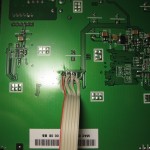
Serial Header with Ribbon Cable

To communicate with the bootloader, we need a serial port. Once you open the NSD-100 there is an obvious single unpopulated header, which serves as the serial port. All you need to do is solder on a ribbon cable on the underside of the board, and you get a 3.3V TTL level serial port. By soldering a ribbon cable on the underside of the board, there is no need to remove the EMI shield on the top side of the board.

Continue reading

PolyController

So I’ve been working on a bit of a pet project lately – which I’ve been calling the PolyController. Slightly fed up with our central heating controller and thermostat being so stupid, I thought I could do better myself and build my own. Our current controller is nothing but a time switch, and the thermostat a manual dial one that has unfortunately been mounted right next to the main central heating feed pipes and hence is mostly useless.

The idea started with a simple microcontroller operating 4 relays and getting fed temperature information over the network from my already existing 1-Wire temperature sensors. My thoughts were to run a simple program to feed the controller the temperature information and it could determine whether the central heating and/or hot water needed to operate. A simple schedule could determine if/when heat was needed and what temperature to aim for – that way you could keep the heating on at a lower level during the night for example, or offer frost protection when you’re on holiday.

Continue reading