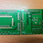
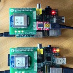
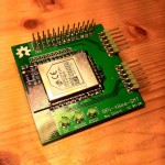
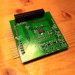
During the course of this week, I have received my XBee PCBs (right) and started playing with them!
First of all, I’d like to say thanks to the folks at Seeed Studio / Fusion PCB whose service I used to fab these boards. I went for the slightly more expensive ENIG finish on these, but they were still very reasonably priced and have come out very well indeed. I would definitely use them again.
So anyway, after a quick order for some extra TC2117 regulators that I found I ran out of, and a fistful of LEDs and that sort of thing, I built two backpacks up complete with XBee modules and set out to get them to talk. This was my first foray into the world of XBee / ZigBee so was a very interesting process!
After upgrading the firmware on the modules using X-CTU and my trusty FTDI cable (with the modules on the backpacks), I set one up as a coordinator and connected them up (using the AT commands) so that they had a sort of serial session open between them. I then put jumper wires across the TX/RX lines on the two FTDI connectors on one module, and I had a wireless serial console to my other RPi!
 Features
Let’s talk about what my backpacks can do:
- Use a Digi XBee ZB SMT with your Raspberry Pi, thus joining your Raspberry Pi to a ZigBee network – either as a coordinator or as a router.
- You could also use a “normal” XBee module (or compatibles) with the standard headers also included.
- Communicate with the module using SPI (ZB SMT only) or TTL serial (after bridging two solder jumpers).
- Two FTDI compatible headers are included, one for the Raspberry Pi’s serial console and one for the XBee module. Fully compatible with X-CTU for configuration and firmware upgrades.
- Three LEDs are included for OK, Association and RSSI.
- Solder jumpers for configuration:
- SPI chip select line (CE0 or CE1 or none)
- Interrupt line (GPIO4 or GPIO17)
- DTR / Sleep Request line (GPIO24 or GPIO25)
- Features an on-board 3.3V regulator so the Raspberry Pi’s own limited 3.3V supply is not used. Alternatively, a solder jumper can bridge the connection to use the Pi’s internal supply.
- If you use a stacking connector (recommended), you still have access to all the pins on the GPIO header for things like I2C or another SPI device!
What next?
Well the hardware is done and appears to work quite nicely. Next, we need a software stack to actually use the ZigBee network in more ways than just a dumb serial console. There is a libxbee that may be useful, though I feel I may end up writing my own library and client/server architecture for use with SPI and UART ZigBee XBees and multiple client programs.
Onwards and upwards!


Looks nice Chris!
Always cool to receive your very own PCB, isn’t it 😉 And the thrill when everything works as planned… aaahh! 🙂
Yeah, when it works first time and doesn’t require any green-wire work it’s rather a revelation! 😀
Pingback: Been away too long « Devworksinprogress's Blog
Great post! You could also have a look to an interesting tutorial about Xbee for Raspberry Pi http://www.cooking-hacks.com/index.php/documentation/tutorials/raspberry-pi-xbee