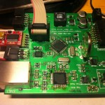
I haven’t posted about this for a while, but the project is definitely progressing. The hardware is complete—PCBs have been manufactured, I’ve soldered them up, and they have been fitted into enclosures. The firmware is also progressing well, though much slower than I had hoped due to being quite busy at the moment! The PCBs have had quite a few minor changes since I last posted pictures, especially on the main controller PCB. Some of the connectors were relocated and quite a few mistakes were fixed before production. Even so, as with almost any first revision PCB, there have been a few mistakes…
The Mistakes!
The first mistake is on the 32.768KHz clock line from the RTC to the AVR microcontroller. The clock output is open drain on the RTC, so this requires a pullup resistor to get a meaningful signal. The AVR I/O port has an internal pullup that can be enabled if required so I thought I could use that, but it turns out that doesn’t work if you use the port as a clock input rather than a general purpose I/O. This is easily fixed with greenwire and a 1K resistor.

