So I’ve been working on a bit of a pet project lately – which I’ve been calling the PolyController. Slightly fed up with our central heating controller and thermostat being so stupid, I thought I could do better myself and build my own. Our current controller is nothing but a time switch, and the thermostat a manual dial one that has unfortunately been mounted right next to the main central heating feed pipes and hence is mostly useless.
The idea started with a simple microcontroller operating 4 relays and getting fed temperature information over the network from my already existing 1-Wire temperature sensors. My thoughts were to run a simple program to feed the controller the temperature information and it could determine whether the central heating and/or hot water needed to operate. A simple schedule could determine if/when heat was needed and what temperature to aim for – that way you could keep the heating on at a lower level during the night for example, or offer frost protection when you’re on holiday.
Of course I discussed the project on IRC and as usual with these things, design by committee steps in! So it got expanded to have its own 1-Wire bus master so it doesn’t have to be ‘fed’ from an external source, and it gained an RTC so it can keep accurate time by itself. Further playing with the software loaded on the microcontroller revealed things were going to be rather tight so I picked a much more beefy ATmega1284 to run it on, and also added a 8Mbit FLASH chip for external storage so that a rather nice web-interface can be easily implemented.
The next thing that came up is that of course we’re playing with mains voltage (up to 240V here in the UK), and you have to take various precautions when dealing with it. Much IRC guidance revealed I had to keep a rather large gap between the mains bits and the low voltage control bits, much larger than I imagined. This led to the circuit ending up too big to be used in my PCB layout program (the free edition limits the size of the PCB) so I had to split it into its own board – the natural progression from there led to the relay boards being daisy-chainable so you can have many more than the 4 relays one board provides.
Finally, the choice of enclosure. I looked around a lot and thought that the project would end up in a single large-ish metal enclosure with the boards attached via stand-offs. It turns out this is quite expensive and labour intensive as you have to get an enclosure and rivet the stand-offs to it. I later discovered some nice snap-fit DIN format enclosures. These are made out of plastic and you have to have a certain size PCB with the connectors only on the top and bottom, but are really rather nice. You can mount them on a standard DIN rail or wall-mount using the same clips – very handy.
So you end up with something that does rather a lot more than it started out doing:
- Central Heating / Hot Water control (or anything that wants to twiddle relays, such as lighting)
- 1-Wire Bus Master (with Ethernet/IP bridge) for sensor attachment (temperature, humidity, light level, etc…)
- 10/100 Ethernet with auto-sensing
- IPv4 or IPv6 capable (sadly not dual-stack)
- Web-based interface for remote control (adjust your heating from abroad!)
- RTC and NTP client for accurate time
- Each relay can withstand 8A current
- Add relay boards (4 relays each) for as many relays as you want
- Fully Open-Source firmware (of course)
- Connector for future expansion (ZigBee anyone?)
The main issue I’ve run into it now is manufacturing it. Producing such a piece of hardware is sadly quite expensive in small volume (building 1 costs over twice as much per unit than building 5, almost 3 times as much as building 10, and almost 4 times as much as 100) so I’ve had to try and find some early-adopters who are willing to buy an unfinished product (it only exists on paper for now) in order to get the price per unit as low as possible.
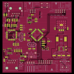
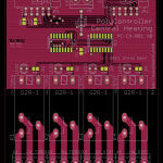
So, without further ado, here are some pretty pictures of the PCBs as they are currently laid out:
- PolyController Main Board
- PolyController Central Heating
Interested in obtaining one of these? Let me know using the email address at the bottom of this page.


