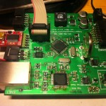
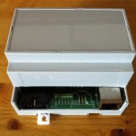
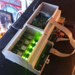
I haven’t posted about this for a while, but the project is definitely progressing. The hardware is complete—PCBs have been manufactured, I’ve soldered them up, and they have been fitted into enclosures. The firmware is also progressing well, though much slower than I had hoped due to being quite busy at the moment! The PCBs have had quite a few minor changes since I last posted pictures, especially on the main controller PCB. Some of the connectors were relocated and quite a few mistakes were fixed before production. Even so, as with almost any first revision PCB, there have been a few mistakes…
The Mistakes!
The first mistake is on the 32.768KHz clock line from the RTC to the AVR microcontroller. The clock output is open drain on the RTC, so this requires a pullup resistor to get a meaningful signal. The AVR I/O port has an internal pullup that can be enabled if required so I thought I could use that, but it turns out that doesn’t work if you use the port as a clock input rather than a general purpose I/O. This is easily fixed with greenwire and a 1K resistor.
The second problem is I laid out the two RJ45 connectors (for Ethernet and 1-Wire) on opposite sides of the board and made both stick out of the sides of the board by 2mm—the thickness of my enclosure—which means they look a bit better and are easier to use once the board is in its enclosure. The problem with that is I can’t put the board in the enclosure with both connectors soldered on, instead I have to leave one of them off, put the board in the enclosure, then solder on the 1-Wire connector.
Finally, it looks as though I may have wired up my Ethernet port with the wrong wiring. By this I mean the connector may have the TX and RX lines crossed so it requires a crossover cable to work. I’m not entirely certain of this, as the only non-auto-MDI/X device I have is my Snom 300 phone, which may have the wrong sort of port itself. I went over my schematic several times and can’t see a problem. Thankfully it works just fine other than this, and as most switches are auto-MDI/X these days this shouldn’t be a problem. If it is, you can just use a crossover cable instead.
The Firmware
The firmware is coming along nicely. It uses the Contiki Operating System as a base, but replaces the build system and rewrites/adapts many of the bundled applications and libraries to work better for this project. Things I’ve got working so far:
- Hardware Drivers:
- AT26DF081A SPI Flash Chip
- DS1307 RTC
- DS2482-100 1-Wire Master
- ENC424J600 Ethernet Controller
- I2C Bus (used by DS1307 and DS2482)
- SPI Bus (used by SPI Flash and ENC424J600)
- SN74HC595 Shift Register (used on the relay board)
- Serial UARTs (serial ports)
- Wallclock (internal counter attached to DS1307 clock output)
- Libraries / Utilities:
- Applications:
- Console shell—over serial or telnet, tools like cat, ls, free (memory info), date, netstat, tftp firmware upgrades, test tools for 1-Wire and the relay boards.
- Webserver—serves up static files at the moment, and has an SSI-style include ability. Will expand to have a CGI-style ability to get/set settings and status via XHR/JSON.
- DHCP
- Monitor—blinks LEDs for certain events, including a heartbeat LED.
- owfsd—permits owfs to use the built-in 1-Wire master (as well as internal tools).
- DNS resolver.
- Syslog—for logging to a remote syslog server.
- Timesync—ties together the RTC, internal Wallclock timer, and NTP to keep accurate track of time.
- Bootloader—hardware bringup and firmware upgrades.
You may notice that at the moment there is a distinct lack of heating controller ability in the PolyController. About the only useful functionality at the moment is the interface to owfs, which lets you run a complex 1-Wire network using the PolyController as a master; this works very well indeed.
Next up are the improvements to the web server to make the system configurable over the web, including networking configuration (static IPs, NTP servers, syslog, etc…) and much more. The heating control will be the next big part of the jigsaw.


